Home End
FIELD WALKING – Laying out a 10 m Grid
There are various ways of laying out a grid, this notes describes one of the simplest in that the only equipment needed is 2 tapes.
The main problem in laying out a grid is in ensuring that the grid is square. The method used here is based on the fact that a square of 10 m has a diagonal of length 14.14m. . The same method can be used for larger squares as follows.
A 10 metre square has a diagonal of length 14.14 metres.
A 20 metre square has a diagonal of length 28.28 metres.
A 30 metre square has a diagonal of length 42.42 metres.
A 50 metre square has a diagonal of length 70.71 metres.
Equipment Needed
2 tapes - 1 at least 10 m and one at least 15m, it is easier if both are 15m.
Canes – The more the better. You should have at least enough canes to mark out 2 complete lines across the field. It is useful to have some brightly coloured tape or other material (plastic carrier bags?) to fix to the top of the canes to make them more visible.
Optional Equipment
Compass - this can be used to record the orientation of your grid .
GPS receiver - to record the grid reference of your grid. Note this is only accurate to about 10m.
Large scale map
Optical Square - This is a specialist piece of equipment for defining right angles and straight lines.
Procedure (see diagram below)
First define a base line for the grid. The base line needs to be defined so that it can easily be reproduced in the future incase further work needs to be done on the field. . If the field has a straight edge it is generally sensible to have the base line against this edge. Try to relate the base line to some fixed points that are not likely to disappear such as a large tree or a building.
Once the location of the base line has been decided lay out the base line using canes at
10m intervals. Make sure that the canes are vertical. Sight along the canes to ensure that the base line is straight. When the base line is complete return to the start of the base line. To locate point D fix 1 tape to point A on the base line and the other tape to point B on the base line. Measure 10m on the tape from point A and 14.14m on the tape from point B. Where these measurements meet is point D. To locate point C measure 10 m along the tape from point B and 14.14m along the tape from point A. Where these meet is point C. This has defined the first grid square. Use point B and the next point on the base line to layout the next grid square. If C is measured from these 2 points then this is a check on its location. Work along the base line to layout the first row of grid squares. As each of these grid squares is laid out sight along the line DC to ensure that it is straight. When this row of grid squares is complete the line though DC forms the base line for the next row of grid squares.
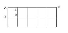 AZ is the base line. ABCD is the first grid square
It is important that each point in the grid is measured as accurately as possible. Each row of the grid is based on the previous row so any errors will increase as you work across the field. One check on errors is to keep sighting along the rows and columns of the grid to check that all the lines are straight.
Appendix 1 – Pythagoras's Theorem
Pythagoras's Theorem states that the square of the hypotenuse (the side opposite the right angle) is equal to the sum of the squares of the other 2 sides.
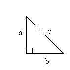 In a right angled triangle as shown on the left c2 = a2 +b2.
So if a and b are both 10 m then c2 = 100 +100 = 200
So c = 14.14 m (i.e. the square root of 200)
Home Top